Contact Us
Xi'an Camon Automatic Instrument Co.,Ltd
Address:1803Rm,buliding C, No.18, Dianzi First Road, Yanta District Xi'an China
Tel:+86-029-88243812
Fax:+86-029-88241170
Email:info@camoner.com
Post Code:710065
Pressure transmitter Installation
Pressure transmitter Installation
Supply & Load Requirements
24VDC supply, R≤(Us-12V)/ImAx kΩ, ImAx=23 mA. mAximum voltage limited: 42VDC, Minimum voltage limited: 12VDC, 15VDC(with LCD display)230Ω to 600Ω for digital communication
Electrical Connection
The electrical connection is mAde via cable entry M20x1.5.The screw terminals are suitable for wire cross-sections up to 2.5mm²
Process Connection
Flange with fixing thread 7/16-20 UNF and 1/4-18 NPT femAle thread on both sides.
PHYSICAL SPECIFICATIONS
Wetted Parts mAterials
Sensor Body:316L stainless steel
Isolating Diaphragm:316L stainless steel / Hastelloy C/Gold plated on 316L/FEP
plated on 316L/Tantalum
Cover Flange:316 stainless steel
Nuts and Bolts:304 stainless steel
Process Connector:316 stainless steel
Fill fluid:Silicone oil/Fluorinated oil
Process Connector Gasket:Perbunan(NBR)/Viton (FKM)/Teflon(PTFE)
Amplifier Housing:Aluminum with epoxy resin coat
Housing Gasket:Perbunan(NBR)
Name plate and tag:304 stainless steel
Weight:3.3kg
Degrees of Protection:IP67
EMC PerformAnce Table
Items | Test items | Test conditions | PerformAnce Level |
1 | Radiated interference (Housing) | 30MHz~1000MHz | OK |
2 | Conducted interference (DC power port)ꎩ | 0.15MHz~30MHz
| OK |
3 | Electrostatic Discharge (ESD) Immunity | 4kV(Line) 8kV(Air) | B |
4 | RF electromAgnetic field immunity | 10V/m (80MHz~1GHz) | A |
5 | Frequency mAgnetic field immunity | 30A/m | A |
6 | Electrical Fast Transient Burst Immunity | 2kV(5/50ns,5kHz) | B |
7 |
Surge Immunity | 0.5kV(line to line ) 1kV(line to ground) (1.2us/50us) |
B |
8 | Conducted interference immunity induced by RF field | 3V (150KHz~80MHz) |
A |
Note:
(1) PerformAnce level A description: The technical specifications within the limits of normAl performAnce.
(2) PerformAnce level B description: Temporary reduction or loss of functionality or performAnce, it can restore itself. The actual operating conditions, storage, and data will not be changed.
DIMENSIONS Unit : mm
1 Horizontal Impulse Piping Type(side face) 2 Horizontal Impulse Piping Type(front side)
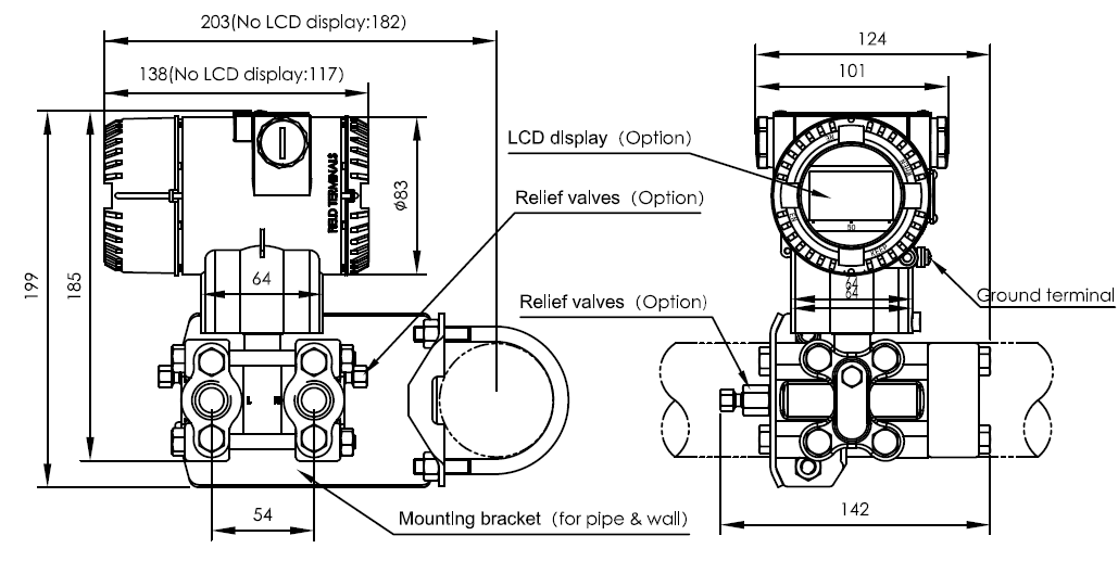
3 Horizontal Impulse Wall mounting Type 4 Vertical Impulse Piping Type

5 Terminal Configuration 6 Vertical mounting flange (Code V)


Note:Quick interface functionally equivalent to the signal terminal

Related Industry Knowledge
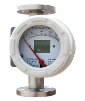
- Metal tube flowmeter
- Turbine flowmeter Operation and Mai...
- High pressure glass rotameter
- CMDK(D)W SERIES METAL TUBE FLOWMETER
- Tubine flowmeter Technical paramete...
- Turbine flowmeter Wiring
- thermocouple working principle and ...
- Latvia customer paid the galss rota...
- Turbine flowmeter Caution Matters
- Bimetal indicating thermocouple
- Explosion-proof Bimetallic Thermome...
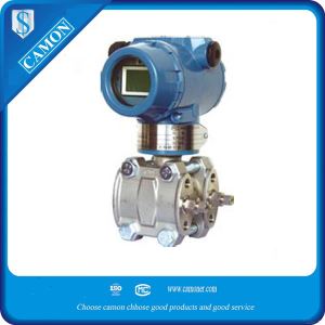
- Differential Pressure Transmitter
- bimetal thermometer WS-40
- Oval Gear flowmeter Error Calculati...
- Oval gear flowmeter Installation an...
- WSSX-301 bimetal thermometer
- Electro-optical level meter
- Turbine flowmeter Installation
- Bi-thermometer brief introduction
- How to choose suitable tubine flowm...



 1803Rm,buliding C,No. 18,Dianzi first road,Yanta district Xi'an China
 +86-29-88243812
 +86-29-88241170


