Contact Us
Xi'an Camon Automatic Instrument Co.,Ltd
Address:1803Rm,buliding C, No.18, Dianzi First Road, Yanta District Xi'an China
Tel:+86-029-88243812
Fax:+86-029-88241170
Email:info@camoner.com
Post Code:710065
Electromagnetic Flow meter Working Principles
Electromagnetic Flow meter Working Principles
1.Measuring Principles
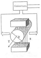
The measuring principle of electromagnetic flowmeter is based on the electromagnetic induction law of Farady.
The sensor is mainly composed of measuring tube with isolate lining, a pair of electrodes installed by penetration
of the measuring tube wall, a pair of coils and iron core to produce working magnetic field. When the conductive
fluid flows through the measuring tube of the sensor, the voltage signal in direct proportion to the average flow
velocity of the fluid will be inducted on the electrodes. The signal is amplified and treated by the transmitter to
realize various display functions.
2.Converter Circuit Schematic
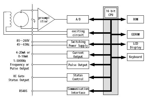
The converters supplies a stable exciting current to the coil in the sensor of electronetic flowmeters to get
B constant and amplifies the electromotive force and convert it into standard signals of current or frequency
so that the signals can be used for displaying, controlling and processing. The schematic of converter circuit is
shown in Fig.1
Related Industry Knowledge
- Intelligent radar level meter
- Turbine flow meter Selection of con...
- Electromagnetic Flow meter specifi...
- Mechnical flow meter
- Selecting The Right Thermometer Par...
- Ultrasonic level sensor
- Metal tube Float Variable Area Rota...
- Selecting The Right Thermometer Par...
- Selecting The Right Rotameter Part ...
- Electromagnetic Flow meter technic...
- Selecting The Right Glass Rotameter...
- Magnetic column (magnetic column) l...
- Siemens SULTRAMAT 23 Gas Analyzer
- Selecting The Right Glass Rotameter...
- Input level transmitter
- Metal tube flow meter Technican Par...
- Selecting The Right Glass Rotameter...
- Selecting the Right Glass Rotameter...
- Turbine flow meter Installation Cau...
- Use of pressure transmitter



 1803Rm,buliding C,No. 18,Dianzi first road,Yanta district Xi'an China
 +86-29-88243812
 +86-29-88241170


