Contact Us
Xi'an Camon Automatic Instrument Co.,Ltd
Address:1803Rm,buliding C, No.18, Dianzi First Road, Yanta District Xi'an China
Tel:+86-029-88243812
Fax:+86-029-88241170
Email:info@camoner.com
Post Code:710065
Turbine flow meter Installation Caution
Tubine flow meter Installation Caution
1) Installation area
The installation area should be in conformity with a temperature range of -25~+55℃,a humidity<80%RH(non- condensing)
Good ventilation, free of solarization and rain.
A place free of vibration or stress from piping.
Avoiding a place apt to strong heat radiation and radioactive impacts
The disturbance of detection signal resulted from outside strong electromagnetic field must be avoided.If such disturbance can not be averted, such measures as a shield enclosure should be added on the amplifier of the flow meter (transducer) to eliminate interferences.
At a place requires explosion proof measures, explosion suppression amplifiers shall be applied.
The installation position should be tailored to easy installation, operation and maintenance.
1) Installation posture and position
In order to ensure a high measuring accuracy, the flow meter (transducer) shall be horizontally installed on a horizontal pipeline, and the arrow sign on the flow meter that indicates the flow direction shall be made consistent with the liquid flow direction.In case a vertical installation is a must, the liquid shall be made flow from the down to top, so that the body of the flow meter will be ensured full of liquid.
2)Piping requirements
0 To eliminate influences of the measuring accuracy resulting from uneven flow velocity distribution of cross section inside a pipeline, both the upperstream and the downstream of the flow meter shall be installed with definite straight lengths, or be installed with flow straighteners to substitute some straight lengths.
Normally, the upperstream straight length shall be no smaller than 15D, and the downstream straight length no smaller than 5D (D stands for the nominal diameter of the flow meter.).In normal cases, the recommended upperstream straight length is given below:
Concentric reducing pipe: L=15D(Figure 7-1a);an elbow smaller than 45°:L= 20D
Figure 7-1b);double 45°elbows in the same plane:L= 25D(Figure 7-1c); double
space 45°elbows:L= 30D;right angle elbow:L= 40D(Figure 7-1d);full-opening
gate valve:L= 20D,half-opening gate valve:L= 50D(Figure 7-1e)。
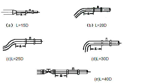
In order to eliminate the influences of reverse flow, uneven flow velocity distribution and rotational flow, flow straighteners may be installed in the upperstream of the flow meter( please see Figure 7-2 for structure of such flow straightener.), in that case, the straight length in the upperstream of the flow meter L=10D will be OK. If the length is 15~20D, the measuring accuracy may meet the calibrated accuracy.
When the measured liquid contains solid impurities, a filter shall be installed in the upperstream of the flow meter, and the filter mesh number shall be 20~60 meshes (3~9mesh/ cm2). In case of a small diameter flow meter,the mesh number will be bigger.When determining the installation position of the filter, easy removal and fitting of filter screen shall be considered.
When the liquid is mixed with gases or when measuring a liquid prone to gasification, an air separator (eliminator) shall be installed.
If the measured liquid is prone to gasification, in order to prevent cavitation, pressure at the outlet end of the flow meter shall be higher than the calculated value Pmin in the formula below:
Pmin = 2△P + 1.25Pv
In the formula: Pmin— Minimum pressure; △P— Pressure loss of flow meter under the maximum flow;
Pv— Saturated steam pressure of the measured liquid under the maximum operating temperature
● An excessively big flow passing through the flow meter will result in an excessively short life of the bearing. Normally, the flow is regulated to a proper level with a valve, which shall be installed in the downstream of the flow meter.
●In order not to interrupt fluid transmission during an overhaul, shut-off valves will be installed in both the upperstream and downstream of the flow meter, and besides, bypass pipelines will be laid. And it shall be ensured that there is no leakage from the bypass pipelines when the bypass valves are closed during the measuring process.
The typical installation of a pipeline system for a flow meter is as shown in Figure
7-3.

Figure 7-2 Figure 7-3
In case of a possible reverse flow, a check valve should be added, so as to prevent reverse flow of fluids.
The flow meter’s body should be concentric with the pipeline, and the seal ring should not protrude into the pipeline.
In order to avoid accumulation of gases inside the flow meter, it shall not be installed at the highest point of a horizontal pipeline.
If the flow meter is installed at a low point of the pipeline, the pipeline shall be installed with a discharge valve to discharge sediments on a regular basis.
The front and back pipeline of the flow meter should be firmly supported, without any obvious vibration.
When cleaning a newly laid pipeline, a short pipe should first be connected to the position where the flow meter will be installed, and after the cleaning, the flow meter will be installed.
Related Industry Knowledge
- Electromagnetic Flow meter Working...
- Selecting The Right Glass Rotameter...
- Selecting The Right Glass Rotameter...
- Magnetic column (magnetic column) l...
- Siemens SULTRAMAT 23 Gas Analyzer
- Selecting The Right Glass Rotameter...
- Input level transmitter
- Metal tube flow meter Technican Par...
- Selecting The Right Glass Rotameter...
- Selecting the Right Glass Rotameter...
- Use of pressure transmitter
- Electromagnetic Flow meter Installa...
- Rotameter Installation Notice



 1803Rm,buliding C,No. 18,Dianzi first road,Yanta district Xi'an China
 +86-29-88243812
 +86-29-88241170


