Contact Us
Xi'an Camon Automatic Instrument Co.,Ltd
Address:1803Rm,buliding C, No.18, Dianzi First Road, Yanta District Xi'an China
Tel:+86-029-88243812
Fax:+86-029-88241170
Email:info@camoner.com
Post Code:710065
Turbine Flowmeter output signal frequency
Turbine Flowmeter output signal frequency: (at lower limit of flow) not lower than 20Hz
(2) Type LWF-P-2 pulse output pre-amplifier is a preamplifier featuring strong load capacity and adaptability of power supply source,
and it may provide reliable pulse signals to PLC.
For wiring connection, please see Figure 8-1, in which +12VDC is modified to +24VDC.
Power supply source: VDD is the nominal value24VDC
Output signal: square wave
Low level:≤1VDC
High level:Power supply voltage VDD-3VDC
(3)Type LWF-P-3 pulse output preamplifier is a preamplifier designed for high temperature conditions of materials and structures of the detector parts on the basis of Type LWF-P-2 amplifier. Under the precondition that the ambient temperature is not higher than 55℃, the medium temperature may come up to 150℃.
preamplifier
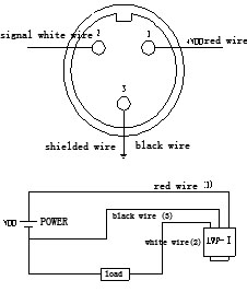
Type LWF-(I)-1 preamplifier output 4~20mA current analog signals, three-wire system. Before leaving the factory, each amplifier has been calibrated together with associated turbine flow meter. In order to ensure the accuracy, mixed use is not allowed.
0 Operating power supply:VDD=+11~26VDC
0 Output signal: current output I=4~20mA
Intrinsic error :±0.5% full scale value
Load resistance:0~RΩ(R=50(VDC-11)+250)
Operating condition: ambient temperature:-25~+55℃;
Relative humidity> 85%RH
Installation: Installed on the body of flow meter
through M16X1 thread and slightly locked with locknuts.
Figure 8-2 Wiring Connetions
Diagram of Type LWF-I-1
Amplimer
Wiring connections: as per Figure 8-2 Wiring connections Diagram of Type LWF-I-1 Pre-amplifier Figure 8-2 Connection Diagram of Type LWF-I-1 Amplifier
Note: The thick black line is used to shield outside interference and must be earthed!
Previous: Thermal mass flowmeter
Related Industry Knowledge
- Turbine flowmeter Wiring
- Turbine flowmeter Flange connection...
- Turbine flowmeter Thread connection
- Specification Codes Turbine Flow meter
- Turbine flowmeter function
- Micro flow range Metal tube Rotameter
- Turbine flowmeter Caution Matters
- Digital Pressure gauge of ordering
- Thermal mass flowmeter
- Pressure Transmitter with Display P...
- Turbine Flowmeter Wiring
- 2Absolute Pressure Transmitter (AP)
- CM3051S Intelligent PressureTransmi...
- CM-3051 High PerformAnce Differenti...
- Connection cable between Vortex flo...
- Thermal mass flow meter Installatio...
- CAM600 Thermal Mass Flowmeter
- MICRO FLOW METAL TUBE ROTARY FLOWME...
- CMWTR14 Pressure Transmitter with D...
- Intelligent Digital Display Tempera...




 1803Rm,buliding C,No. 18,Dianzi first road,Yanta district Xi'an China
 +86-29-88243812
 +86-29-88241170


